Smart Industrial Test Stand for Electromechanical Validation
End-to-End Design of a 5-Station Parallel Validation System — Electrical Schematic, Cabinet Build, CAN Control Software, and HMI Integration
OVERVIEW
Designed and built a complete 5-station parallel test stand for accelerated validation of hydraulic shaft seals — owning the system end-to-end from AutoCAD Electrical schematic, through 3D mechanical cabinet design in Autodesk Inventor, through hands-on fabrication and wire termination, through CAN-bus control logic and HMI software development. The system validates 5 shaft seals simultaneously per test cycle, bypassing full-scale pump endurance runs and enabling significantly higher validation throughput at a fraction of the resource cost.
SYSTEM ARCHITECTURE

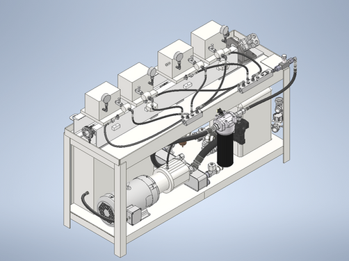
Physical test stand on the validation floor — 5 parallel stations integrated into a single hydraulic, pneumatic, and electrical platform.
Full 3D CAD model in Autodesk Inventor — showing structural frame, hydraulic routing, and station layout.
ELECTRICAL DESIGN & CABINET BUILD
The electrical control cabinet was designed end-to-end: from circuit schematic capture in AutoCAD Electrical, to 3D mechanical sub-panel layout in Autodesk Inventor, to hands-on fabrication and wire termination. The cabinet integrates a SIL 3 / PLe safety relay, 24V DC and 480V 3-phase power distribution, IQAN CAN controllers, Ethernet/IP I/O modules, and operator interface hardware into a single serviceable industrial enclosure.

Full electrical circuit design authored in AutoCAD Electrical — power distribution, control logic, safety circuits, and I/O architecture.

3D mechanical layout of control cabinet sub-panel in Autodesk Inventor — optimized for wire routing, thermal headroom, and serviceability.

DIN rails, safety relay, and I/O modules installed during fabrication — terminal block strips and wire ducts in place.
CONTROL SOFTWARE & HMI
The control software was developed in IQAN Design Studio using CAN J1939 protocol for parameter control, fault detection, and structured data acquisition. The HMI provides operators a real-time dashboard for parameter monitoring, automated fault response, and test sequencing across all five stations.

HMI dashboard simulated in IQAN Design Studio — real-time pressure and temperature readouts across all 5 seal stations.

Fault simulation: temperature exceeded threshold — automatic test shutdown triggered via HMI alert.

Custom CAN J1939 control logic — function blocks orchestrate parameter inputs, fault triggers, and output commands across all stations.
KEY ENGINEERING CONTRIBUTIONS
Accelerated Validation Architecture
Designed a 5-station parallel architecture validating 5 shaft seals simultaneously per cycle, replacing serial full-scale pump endurance runs and enabling significantly higher validation throughput at reduced resource cost.
Functional Safety Integration
Architected a SIL 3 / PLe-compliant safety circuit with redundant safety relays and HMI-integrated diagnostic workflow, achieving a 100% failsafe operator environment per IEC 61508 and ISO 13849.
Multi-Domain System Integration
Synthesized pneumatic, hydraulic, and 480V 3-phase electrical subsystems into a unified test platform with CAN-based control and structured digital data acquisition.

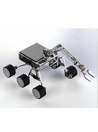
Martian Rover- European Rover Challenge (ERC) & Indian Rover Challenge (IRC) Winner
As Lead Mechanical Engineer for the Suspension & Arm Subsystems (and contributing heavily to overall system integration and strategy), I was responsible for the end-to-end mechanical development of these critical systems. This involved conceptualization, detailed design, rigorous analysis, hands-on fabrication oversight, assembly, testing, and iterative refinement to meet stringent competition requirements and demanding operational conditions
_edited_edi.png)
Robotic Arm Design & Integration (6-DOF)
Led the mechanical design of a 6-Degree-of-Freedom (DOF) robotic arm capable of precise manipulation tasks such as sample collection, tool operation, and equipment servicing.
_edited_edi.png)
CAD Modeling & Detailed Design Documentation
Proficiently utilized SolidWorks and Fusion 360 for all 3D modeling of parts and complex assemblies, managing large assembly files and configurations.

Fabrication, Assembly & Prototyping:
Directed and actively participated in the hands-on fabrication of rover components using various techniques including CNC machining, 3D printing (FDM/SLA), sheet metal bending, and manual machining (mill, lathe).

Advanced Mechanical Design & Prototyping for Hanson Robotics
During my internship at Hanson Robotics, a pioneer in creating expressive and engaging humanoid robots, I joined the Design and Materials Specialist team. My role was deeply embedded in the mechanical engineering aspects of developing and refining components for their advanced humanoid platforms. This involved tackling challenges in miniaturization, precision mechanics, material selection for human-like interaction, and rapid prototyping to bring new functionalities and improved performance to life.

Robotic Joint Backlash Reduction & Mechanism Enhancement:
-
Led a focused effort to decrease joint backlash by 12% for critical joints on the humanoid platform. This involved meticulous GD&T-driven design iterations in SolidWorks, analyzing existing mechanisms, and proposing novel design modifications.

Novel Suspension System Development for Mobile Platform
Engineered novel suspension mechanisms by iteratively prototyping hybrid solutions combining COTS (Commercial Off-The-Shelf) components with custom-designed parts (SolidWorks).
Performed FEA (ANSYS, COMSOL) to analyze load paths, stress concentrations, and deflection characteristics of suspension linkages and spring elements, ensuring durability and desired stiffness.
_edited.png)
General Design Support & Prototyping:
Provided ongoing mechanical design support for various small components and assemblies using SolidWorks.
Extensively utilized 3D printing (FDM, SLA) for rapid prototyping, enabling quick design iterations and functional testing of parts before committing to more expensive manufacturing methods.
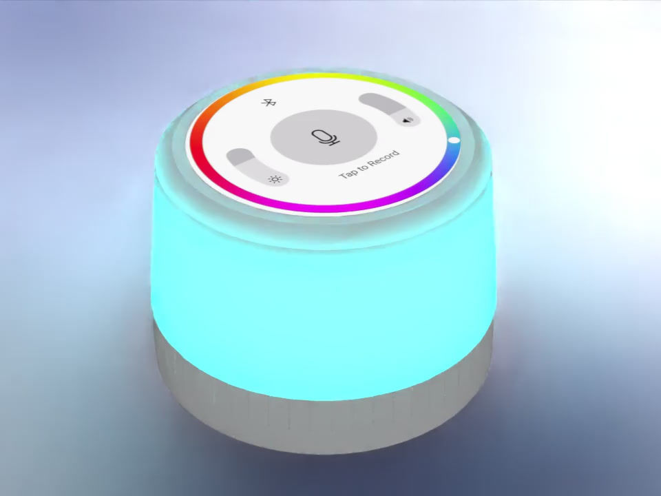
Dreamglow Smart Lamp
DreamGlow was born from a desire to create a multifunctional bedside companion that enhances relaxation and improves sleep quality through a seamless blend of soothing soundscapes, customizable ambient lighting, and high-fidelity audio. This course project allowed me to explore the complete product development lifecycle, from initial concept sketching and user experience considerations to detailed mechanical design, electronics integration, DFM for potential production, and hands-on functional prototyping.

Electro-Mechanical Integration:
Strategically planned the layout for internal components: custom PCB (conceptual), speaker driver, LED modules for ambient light, white noise generation module (conceptual or off-the-shelf), power input (e.g., USB-C), and user interface buttons/touch sensors.
Designed secure mounting features (bosses, snap-fits, brackets) for all internal components, ensuring robust assembly and minimizing vibration.
_edited_edited.png)
Design for Manufacturability (DFM) & Assembly (DFA):
Injection Molding Focus: Primarily designed plastic enclosure parts with DFM principles for injection molding in mind (e.g., consistent wall thickness, draft angles, radii, considerations for parting lines and gate locations).

BOM and Cost Model
To assess manufacturing viability, a preliminary Bill of Materials (BOM) and Cost of Goods Sold (COGS) model was developed. This model estimates material, labor, and overhead costs for high-volume production, providing an early indication of product cost-effectiveness and guiding design-for-cost decisions.

AuraWear - Smart Wellness Tracking Necklace
AuraWear is a personal design exploration into creating a sophisticated yet discreet smart wellness tracking necklace. The vision was to seamlessly blend advanced health monitoring capabilities (conceptual heart rate, activity, skin temperature) with an elegant, fashionable accessory suitable for everyday wear.

Detailed Mechanical Design & CAD (SolidWorks):
Engineered a multi-part pendant enclosure using SolidWorks, employing complex surfacing techniques to achieve an organic and refined exterior while optimizing internal volume for component packaging.
Designed intricate internal features:
Secure mounting bosses and snap-fits for a miniature PCB and integrated sensors (conceptual PPG, accelerometer, thermistor).
A dedicated, vibration-dampened cavity for a haptic feedback motor (ERM/LRA).

Conceptualization & User-Centric Design:
Defined core functionalities and target user experience, focusing on seamless integration into daily life.
Developed multiple form factor concepts through sketching and mood boarding, prioritizing aesthetics, comfort (ergonomics), and intuitive interaction.
.jpeg)
Prototyping & Iterative Validation:
Utilized rapid prototyping (FDM and SLA 3D printing) to create multiple iterations of the pendant enclosure and internal components.
Performed basic tolerance analysis on critical interfaces (e.g., enclosure seal, optical window) to ensure proper fit and function. Applied GD&T principles (ASME Y14.5) on conceptual 2D drawings for key components.
Thermal Analysis of an Automotive Fuel Tank Assembly
This project involved conducting a comprehensive Finite Element Analysis (FEA) to evaluate the thermal performance of a High-Density Polyethylene (HDPE) automotive fuel tank assembly when subjected to a localized exhaust heat source. The primary objective was to identify potential thermal risks, such as excessive temperatures that could lead to increased evaporative emissions (a key concern for EPA/CARB regulations) or compromise material integrity, and to propose effective design mitigation strategies.

CAD Model Preparation & Simplification:
Utilized SolidWorks to prepare the 3D CAD model of the "FUEL TANK ASSEMBLY."
Material Properties & Assignment:
Modeled the fuel tank using High-Density Polyethylene (HDPE).

Simulation Setup & Execution (SolidWorks Simulation):
Steady-State Thermal Analysis: Configured and ran the simulation to determine the temperature distribution once thermal equilibrium was reached. Mention solver used if known (e.g., FFEPlus).
Transient Thermal Analysis (Setup Defined):
Detailed the setup for the planned transient analysis: 9-day duration, adaptive time stepping, and a time-dependent ambient temperature function varying between -20°C and 50°C (e.g., "defined using a sinusoidal time curve function in SolidWorks").
Initial condition: Uniform 300K.
Acknowledged the critical note about resolving previous setup issues before relying on transient predictions.

Macaron Yo-Yo
This UPenn Course project involves the design, iterative prototyping, and small-batch fabrication of 100 custom macaron high-performance yo-yos. The primary goal is not just to create a functional toy, but to conduct a practical study in mechanical design optimization for specific performance characteristics (spin time, stability, responsiveness), explore Design for Manufacturability (DFM) across various materials and processes, and manage a miniature production lifecycle.
%20EXPLODED%20VIEW.png)
Material Selection & DFM Study:
Explored various materials and their implications for performance and manufacturing:
Plastics (e.g., Delrin/POM, Polycarbonate): For injection molding (conceptual DFM considerations like draft angles, uniform wall thickness) or CNC machining from stock.
Aluminum (e.g., 6061, 7075): For CNC machining, focusing on designs that optimize material removal and achieve desired weight and inertial properties.
3D Printing (FDM, SLA): Utilized extensively for rapid prototyping and validating form, fit, and initial spin characteristics with various printable materials.

Rapid Prototyping & Iterative Testing:
Extensively utilized FDM 3D printing torapidly create and test numerous design iterations, allowing for quick evaluation of shape profiles, weight distribution, and ergonomic feel.
Developed simple test setups and methodologies to evaluate key performance characteristics:

Small-Batch Production Planning (For "100 units"):
Outlined a conceptual workflow for producing a small batch (100 units), considering:
Material sourcing and vendor interaction (for bearings, axles, response pads, raw material).
Optimizing 3D print settings for batch production or preparing CAD files for external CNC machining quotes.
Developing a consistent assembly process and basic quality control checks.

Elastic-plastic fracture of medium-carbon steel
in 3-Point bending
This research project focused on utilizing Finite Element Analysis (FEA) with COMSOL Multiphysics to characterize the elastic-plastic fracture behavior of medium-carbon steel in a Single-Edge Notched Beam (SENB) specimen under 3-point bending. The primary objectives were to implement a 2D SENB model, incorporate a Ramberg-Osgood plasticity model, and use the J-integral method to decouple and evaluate the elastic and plastic contributions to fracture toughness. This work is particularly relevant for understanding fatigue-fracture in ductile metals, especially at micron-scales where experimental validation is challenging.

Figure 1 (Schematic of SENB model in COMSOL).
Developed a 2D, stationary FEA model of an SENB specimen in COMSOL Multiphysics.
Implemented material models: Linear Elastic and Nonlinear Elastic (Ramberg-Osgood) to accurately describe plasticity in JIS Grade S45C medium carbon steel.
Defined symmetric boundary conditions, applied point loads, and configured a Crack node with a circular J-integral contour.
Advanced FEA Modeling

Mesh Convergence & Model Validation:
Performed systematic mesh refinement (uniform and crack-tip specific) to ensure solution convergence, achieving J-integral convergence with 2048 elements.
Validated the linear elastic portion of the model by comparing J-integral derived Stress Intensity Factor (K₁) against established theoretical solutions for SENB geometry, demonstrating excellent agreement.
Figure 2 (Mesh refinement and validation plot).

Fracture Mechanics Analysis
Figure 3 (Stress contours and J-integral plots).
Successfully decoupled elastic (Jel or G) and plastic (Jpl) contributions to the total J-integral, demonstrating the ability to quantify plastic deformation effects on fracture toughness.
Analyzed the evolution of crack-tip stress fields and strain energy enhancement due to plastic deformation with increasing crack length.

Problem Solving & Critical Analysis:
Identified and addressed challenges in modeling ductile fracture where traditional linear elastic fracture mechanics (LEFM) is insufficient due to extensive plastic deformation.
Recognized the importance of experimental calibration for obtaining physically meaningful quantitative results from the elastic-plastic model.
Proposed a detailed validation strategy against literature (PMC6546669) for future work.
Figure 4 (Comparison of elastic vs. elastic-plastic stress fields).